
6D40.20 • Interferometers: Fabry-Perot Interferometer
Location: Cabinet 5
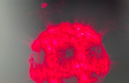
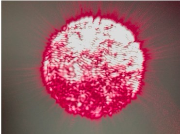
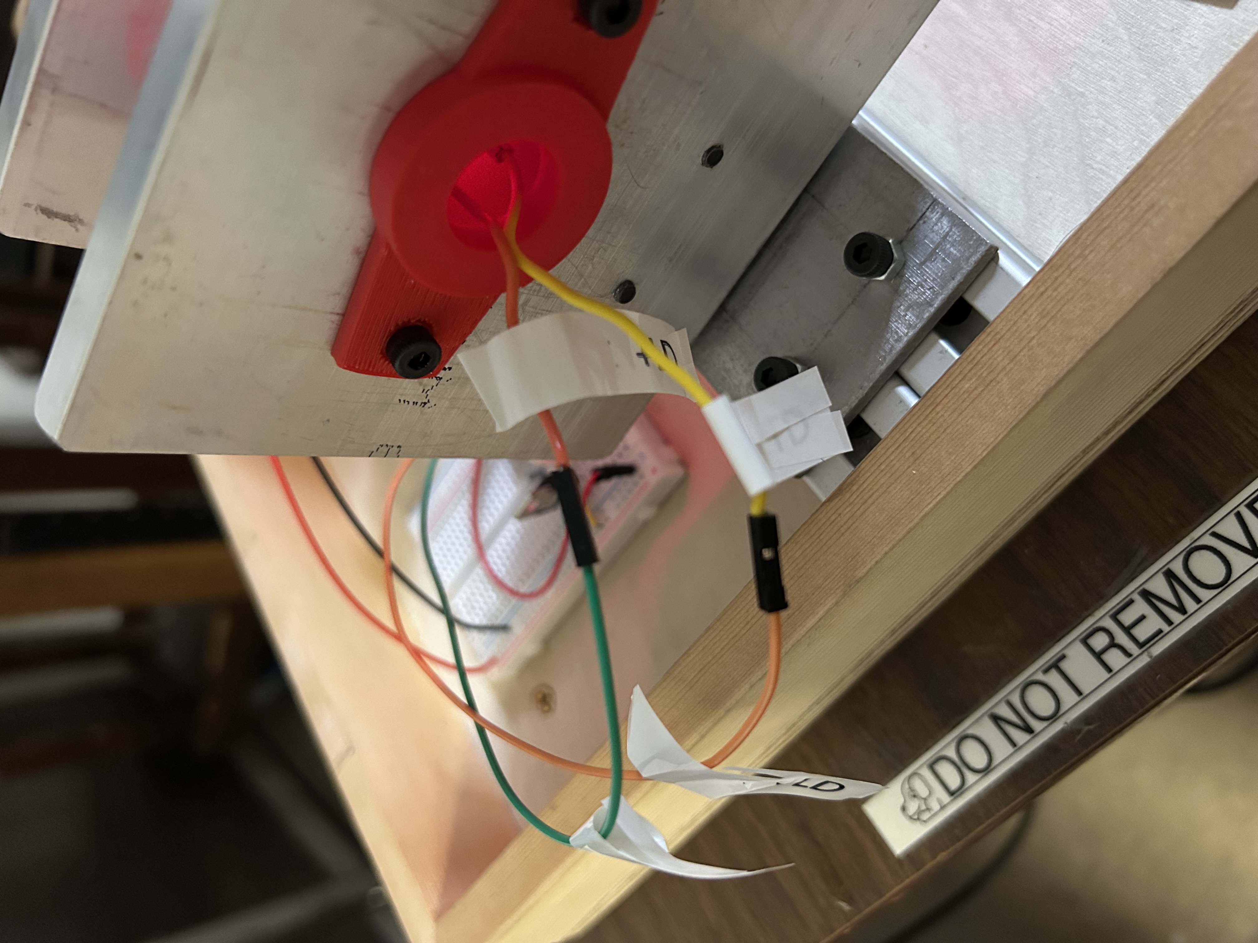
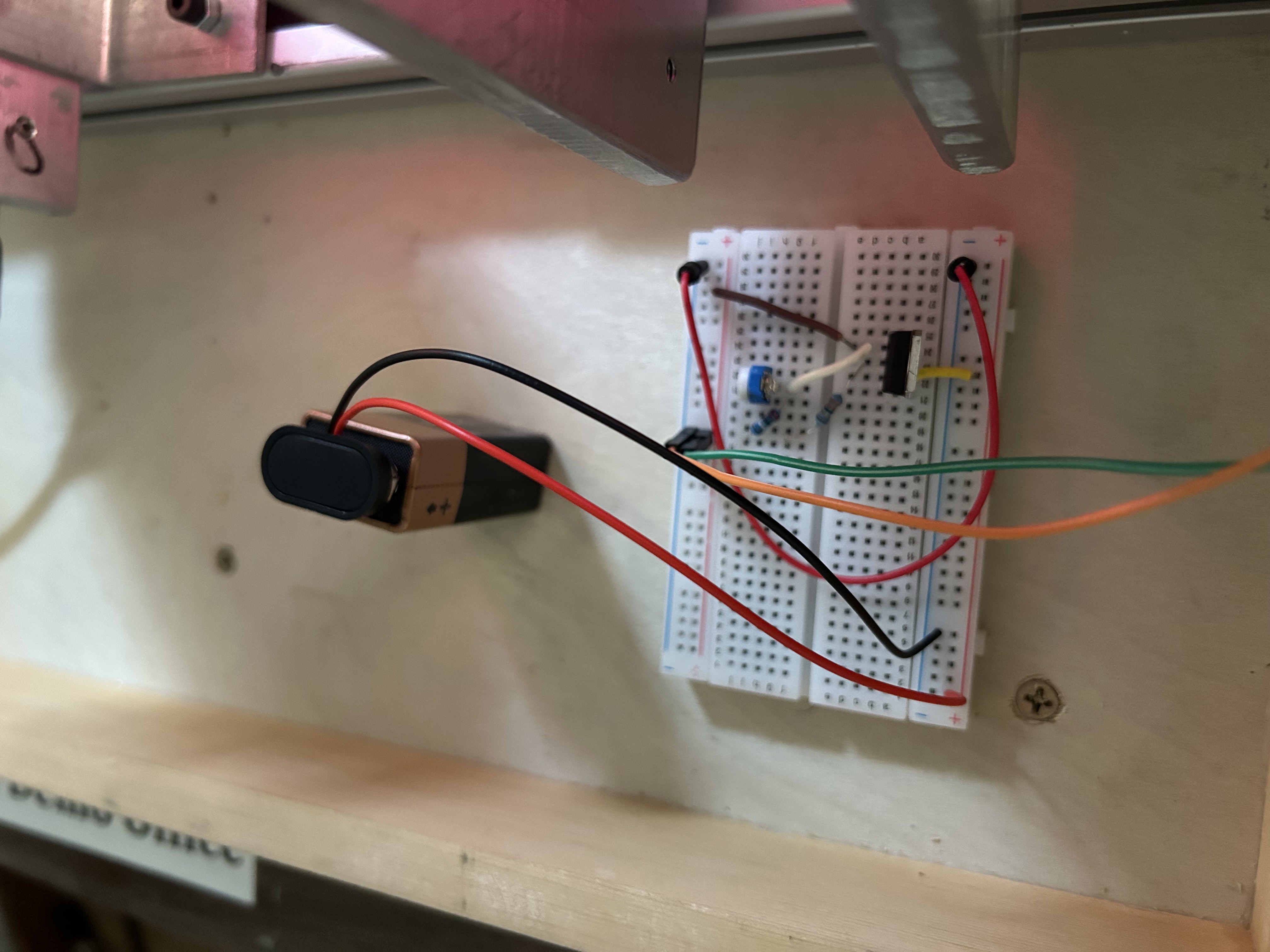
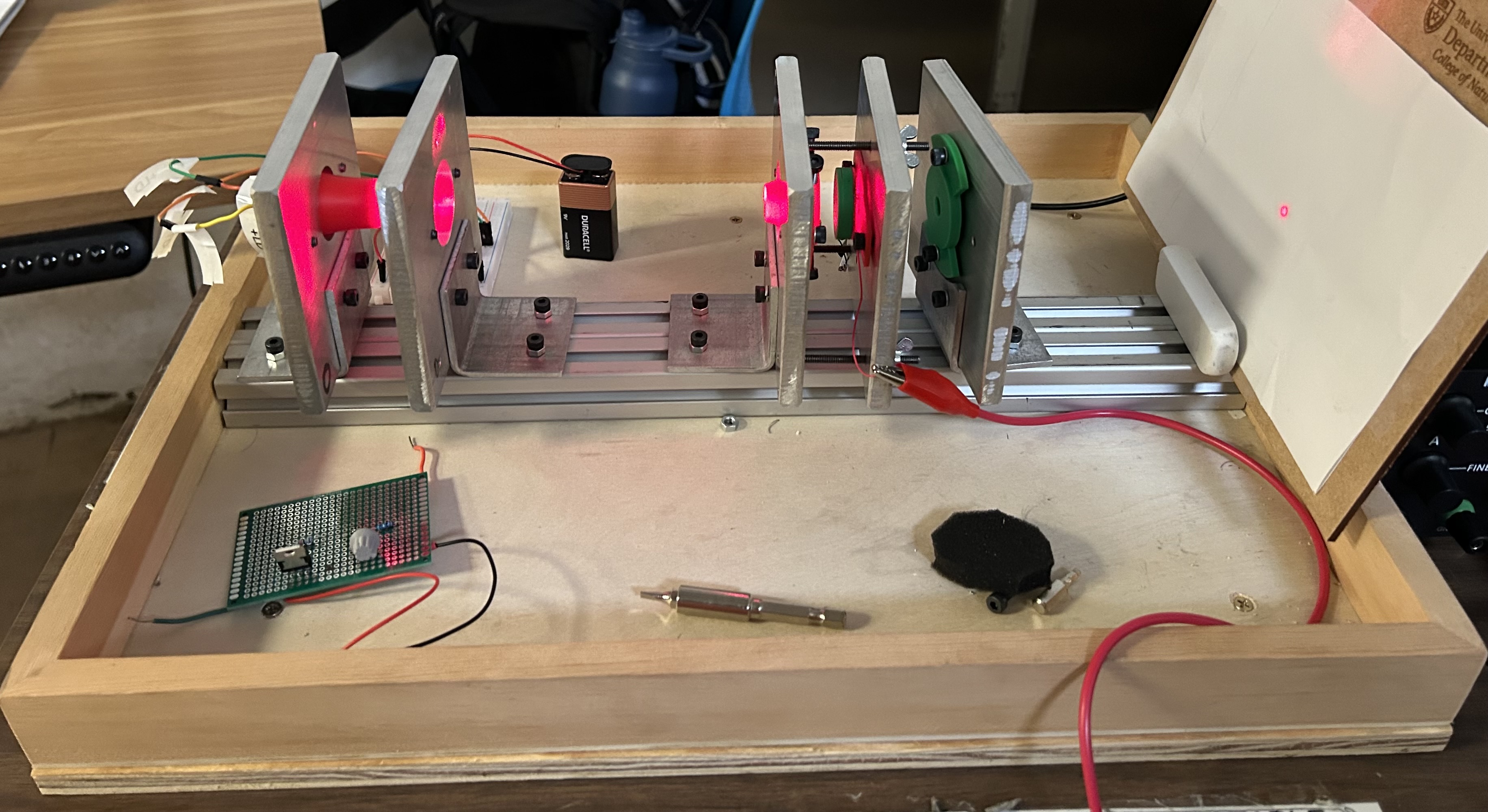
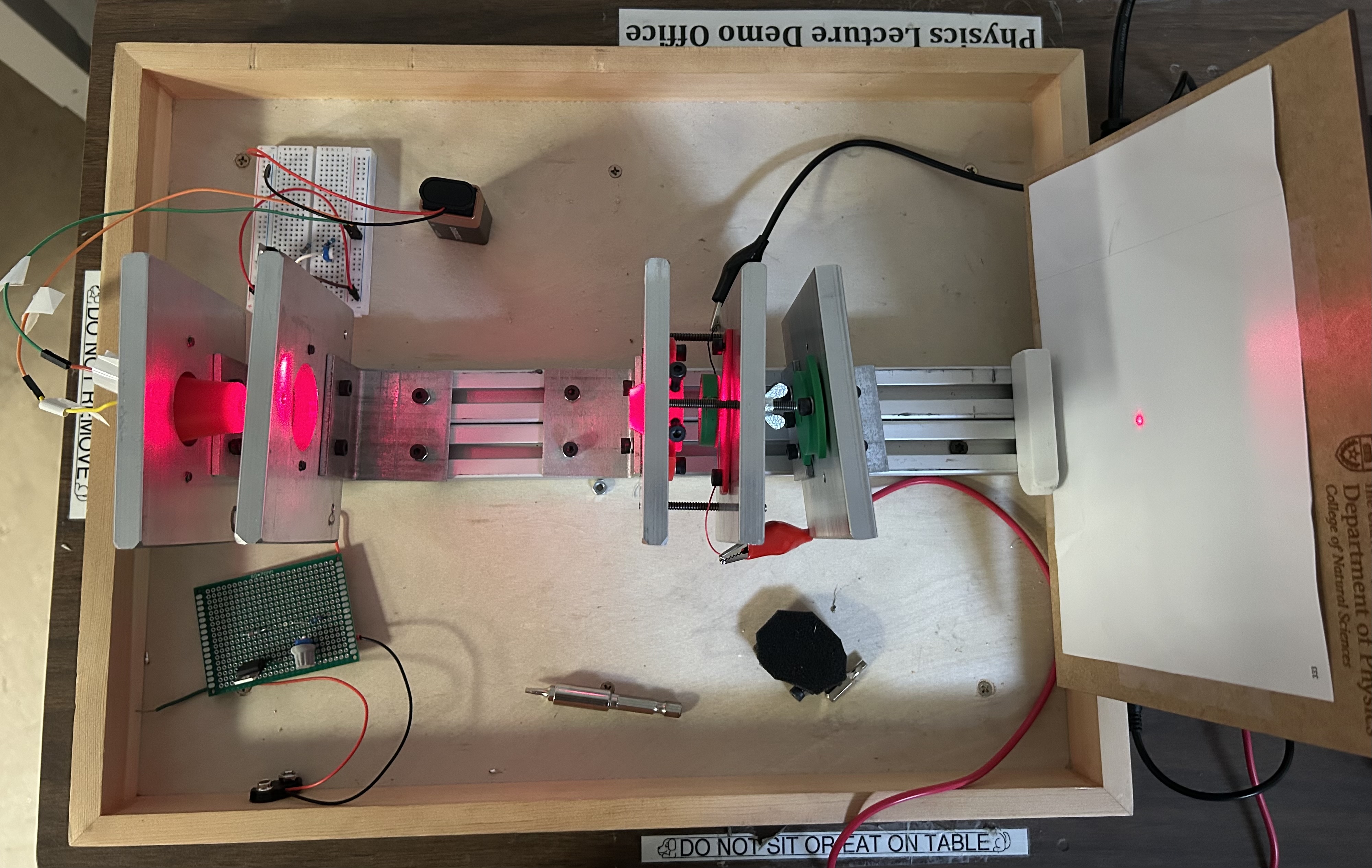
Photo Shows the Demonstration Used at the University of Texas at Austin.
Concepts Conveyed:
- Demonstrate the importance of spectroscopy through a Fabry-Perot interferometer.
- To visualize the changes associated with the interference fringe patterns due to minute movements of the length of the etalon cavity.
Instructions / Notes:
- For the interference pattern to be seen on the viewing screen, the 9V battery’s red and black wires must be plugged into the correct ports.
- The red wire plugs into the positive column, and the black wire plugs into the negative column.
- Once the laser is turned on, remove the black foam covering the aspheric lens to observe an interference pattern on the viewing screen.
- When magnified using an accompanying macro lens (attached to a smartphone), the fringes are seen locally around the grid pattern.
- Additionally, applying a potential across a piezoelectric actuator (via the 30V external power supply), the fringe pattern can shift: the observed fringes are now observed due to multiple beam interferences across the etalon cavity.
Photos of the observed local fringe patterns as seen through a macro lens attached to a smartphone:
Photos courtesy of PHY 341 Building Apparatus class.
Demo staff:
- Setting up the interferometer may be a little tricky, so allow yourself at least 30 minutes before it is requested to properly test it!
- Steps for set up:
- Screw in the aspheric (red) lens in such a way that the diode laser actually passes through the lens and its intensity is maximized (may take some adjusting).
- Attach the orange wire from the white grid to the yellow wire on the track. Similarly, attach the green wire from the white grid to the orange wire on the track. Each wire pair's labels should match up if done correctly.
- Attach the alligator clips to their respective colored wires (found between the stationary beam-splitter and spatially variable beam-splitter) and plug them into their respective colored ports in the 30V external power supply.
- Secure the viewing screen at the end of the metal track.
- Plug the 9V battery's wires into the white grid. The red wire plugs into the positive column, and the black wire plugs into the negative column. Both columns are found on the far-left portion of the grid.
- Unplug these wires once testing is over to prevent the diode laser from overheating! Make sure to instruct the professor on how to plug in these wires properly!
- Finally, turn on the 30V external power supply and remove the black foam from the aspheric lens to allow the laser to fully pass through the cavity. Repeat any above steps for troubleshooting purposes if no laser appears on the viewing screen.
Additional Photos of Demonstration:
Grid wires connected to diode laser wires.
9V battery wires connected to the positive/negative grid columns.
Last updated on July 28, 2026