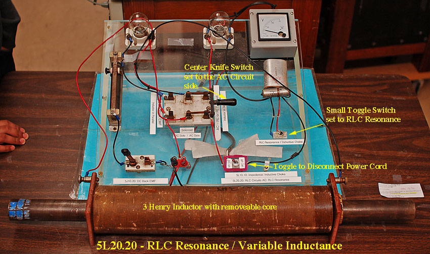
5L20.20 • RLC Circuits AC: RLC — Resonance
Photo Shows the Apparatus used by the University of Texas at Austin.
Instructions / Notes:
- Move the large knife switch in center of the circuit board to the AC
position.
- The large knife switch is used to connect the massive 3 Henry coil to the circuit.
- With it closed in the AC position, the massive coil is part of a RLC Series Circuit.
- Make sure that the small toggle switch under the capacitor is switched to the RLC position. (See the above illustration)
- Again, the Capacitor and Inductor are connected in Series to the light bulb.
- Via a second small toggle switch that is located at the bottom of the circuit board - flip on the main power switch to the AC On position.
- Move the iron core in and out of the ~3 henry inductor coil.
- The light bulb's brightness will indicate the resonance point.
- The provided AC volt meter will read about 40 volts at the resonance point.
- Demo Uses 60 Hz, 120 V, A.C current. Be cautious of what you touch.
- Turn-Off the Main Power Switch After Each Use.
Last updated on March 19, 2018

