5L20.10 • RLC Circuits — AC: RLC Series Circuit Resonance on an Oscilloscope
Photos show the demonstration used by the University of Texas at Austin.

Instructions / Notes:
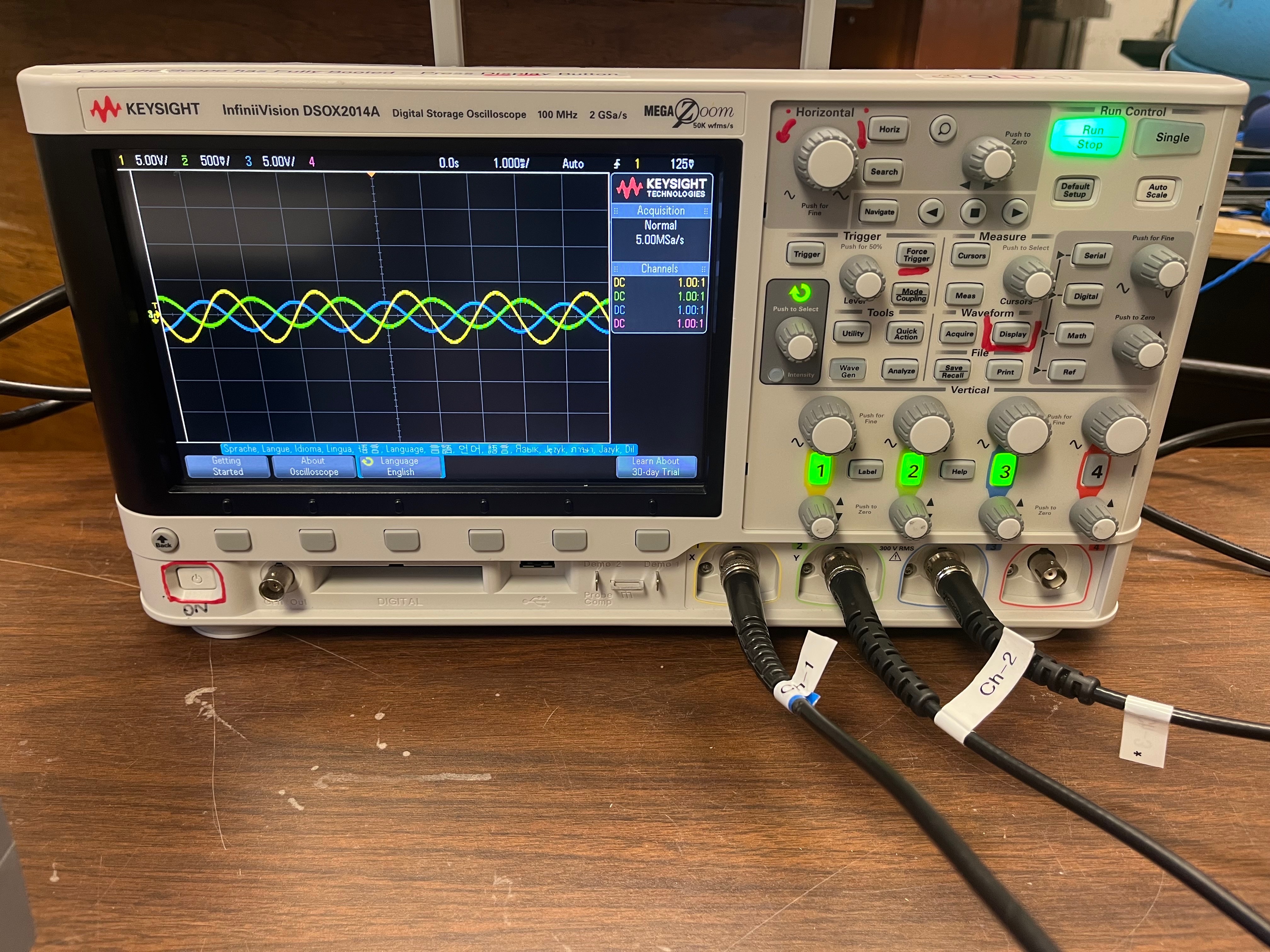
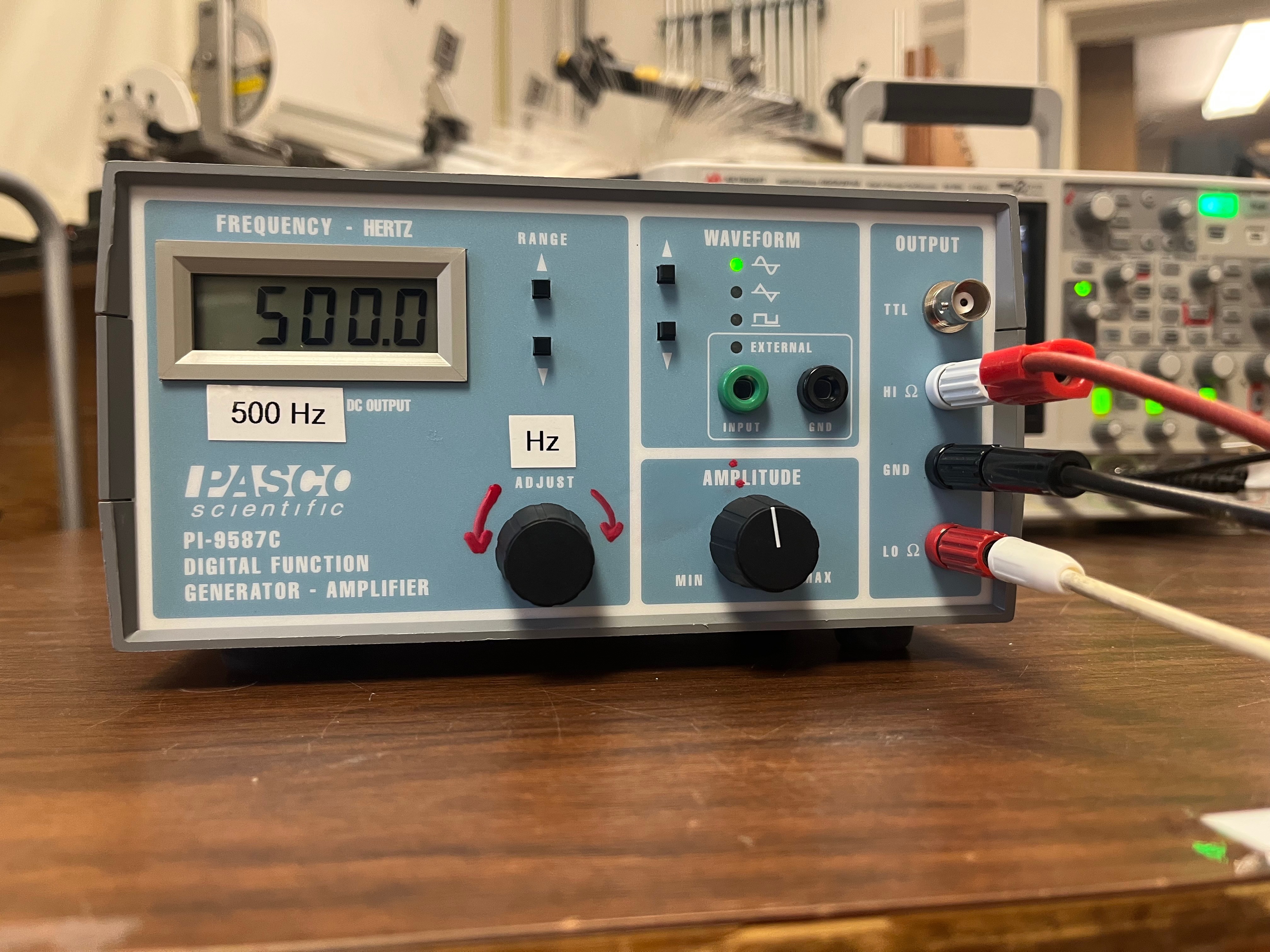
- Demonstration includes a Series RLC Circuit, Pasco Function Generator and an Oscilloscope with a VGA output, which connects to the Lectern A/V system.
- Note: the oscilloscope should be powered through an isolation transformer, (not shown) and the function generator's power cord to use an adapter an isolated ground.
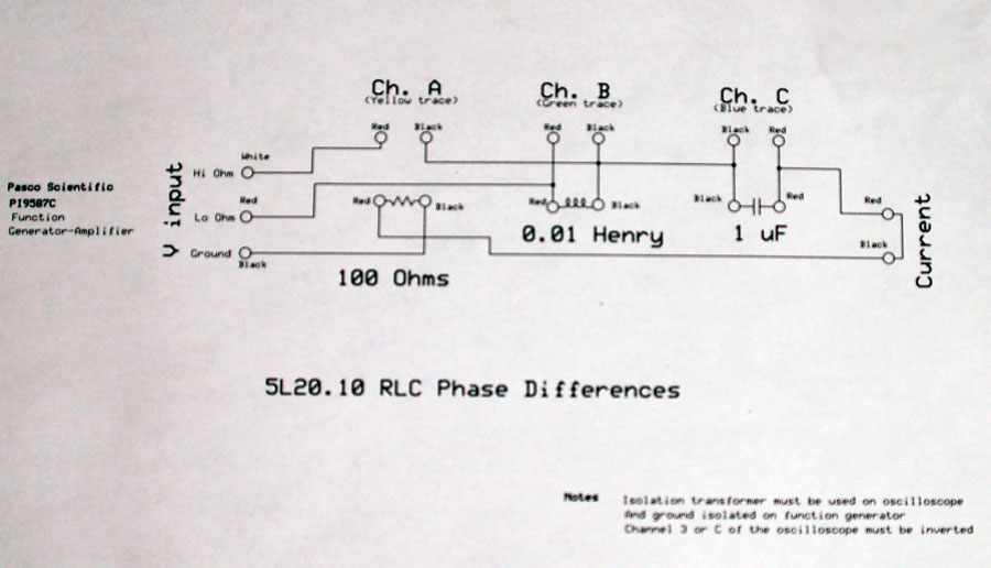
- See the drawing at the bottom of the page.
- While this demonstration was designed to show the phase differences of two separate wave forms as they are measured across the inductor (L) and the capacitor (C) of an RLC circuit - it also can be used to:
- Show the relative amplitudes of the voltage drop across the inductor and capacitor at resonance, which is at 500 Hz, as shown in the above photo.
- Demonstrate the effect on the amplitude of XC versus XL at frequencies that are lower than 500 Hz, (not shown).
- Likewise show the impedance of XL versus XC at frequencies that are much higher than resonance frequency, (also not shown).
- Note: It is recommended that you familiarize yourself with operating this no less than ten minutes before the start of class.
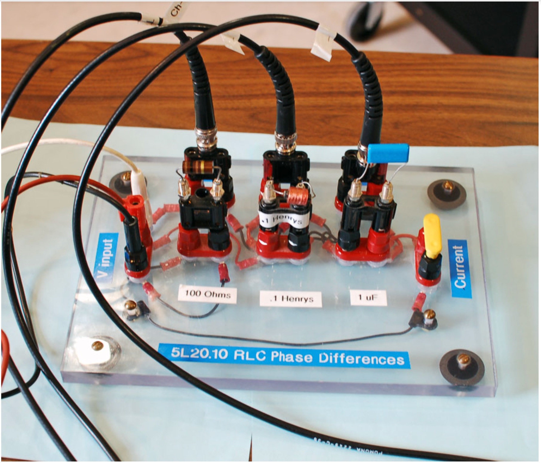
- The values for the components on the above circuit board are 100 Ohms for the resistor, 0.1 Henrys for the inductor and 1 micro-Farad for the capacitor.

- If the demonstration is set to start with a 500 Hz signal - i.e. @ LC resonance - the Horizontal knob needs to be adjusted to 500 micro-second per div.
- The scope's horizontal adjustment will probably need some attention after a major frequency change via adjustment of the Pasco function generator's output.
- Demo Worker Note:For the capacitor, make sure it's invert setting is on. To do this, click on the channel number of the channel where the capacitor is connected, then click on invert.

- The Pasco function generator has an adjustment knob - which has been labelled "Hz" with a red paint pen.
- The triggering for the oscilloscope is a bit iffy when the driving frequency is below 60 Hz.
- High frequency isn't a problem - just remember to adjust the horizontal adjustment on the scope after a frequency reset.
- Make sure to connect the wires exactly as shown in the image.
The Basic RLC series circuit is shown below.

- Note: how the probe connector from Channel 3 BNC cable on the scope is connected to circuit board. It's twin banana plug is reversed.
- At resonance, which 500 Hz, XC and XL have the same amplitudes - but are definitely out of phase relative to each other.
Schematic Drawing of the RLC Circuit after Set Up, (Courtesy of Robert Hasdorff.)
Last updated on November 24, 2024

