5J30.10 • LRC Circuits — DC: LRC Ringing
Photos Show the Demonstration at the University of Texas at Austin.
Faculty Instructions:
- Faculty may change the demo from its default setup (such as moving plugs and adding a capacitor on the circuit board to change damping and frequency of system). However, please Clamp demo to the table with a large C-clamp.
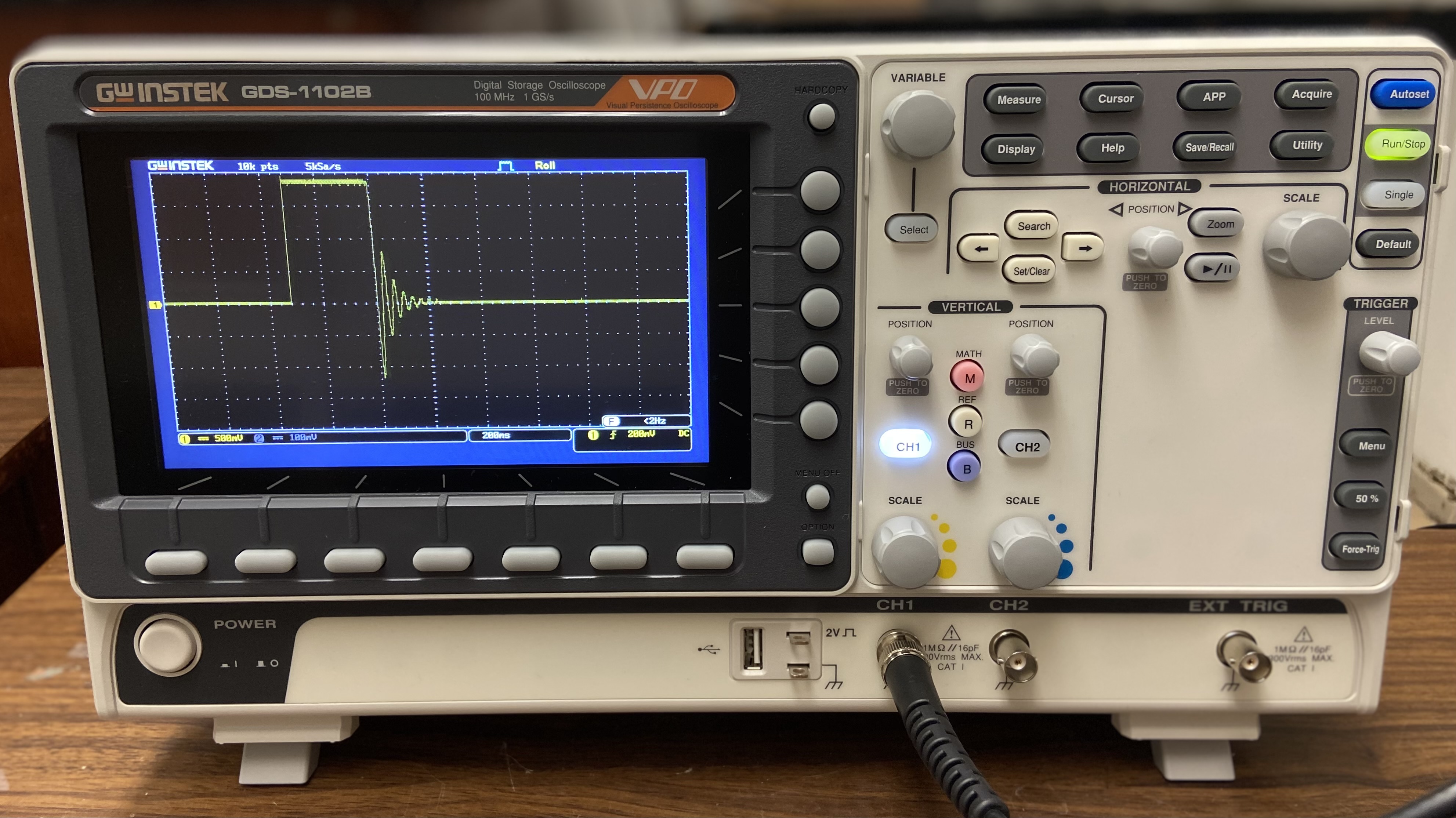
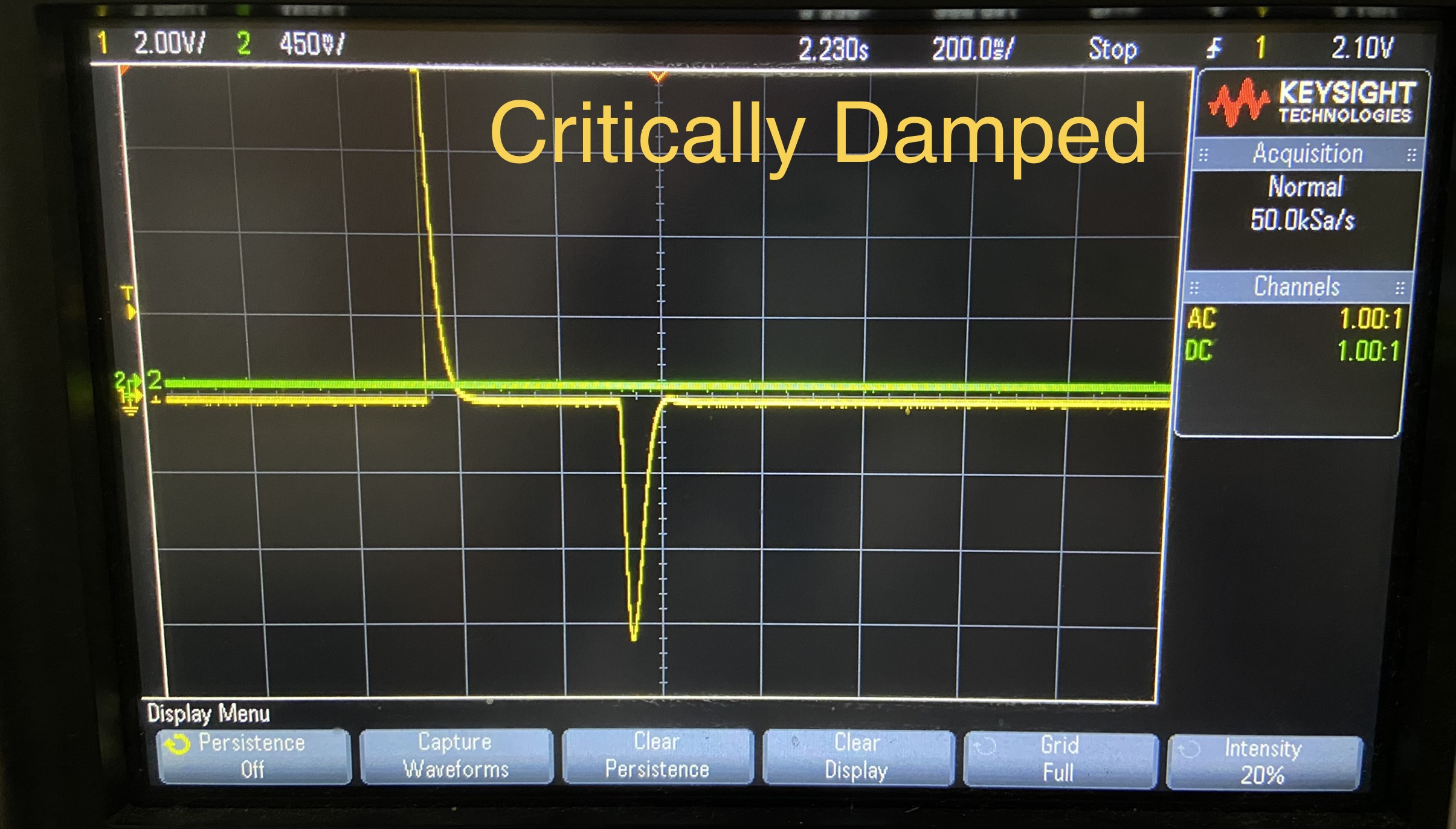
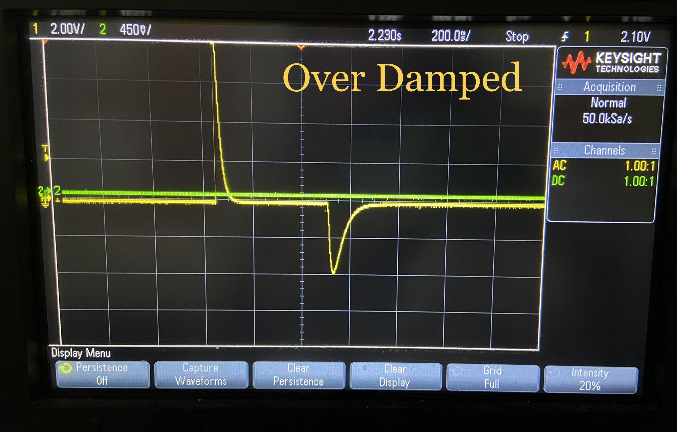
- However, if faculty run into any issues with the demonstration they may double check that the oscilloscope is set to a vertical scale of 500 mV / division and horizontal scale of 200 ms / division. Also ensure the voltage on the power supply is below 2.5 V.
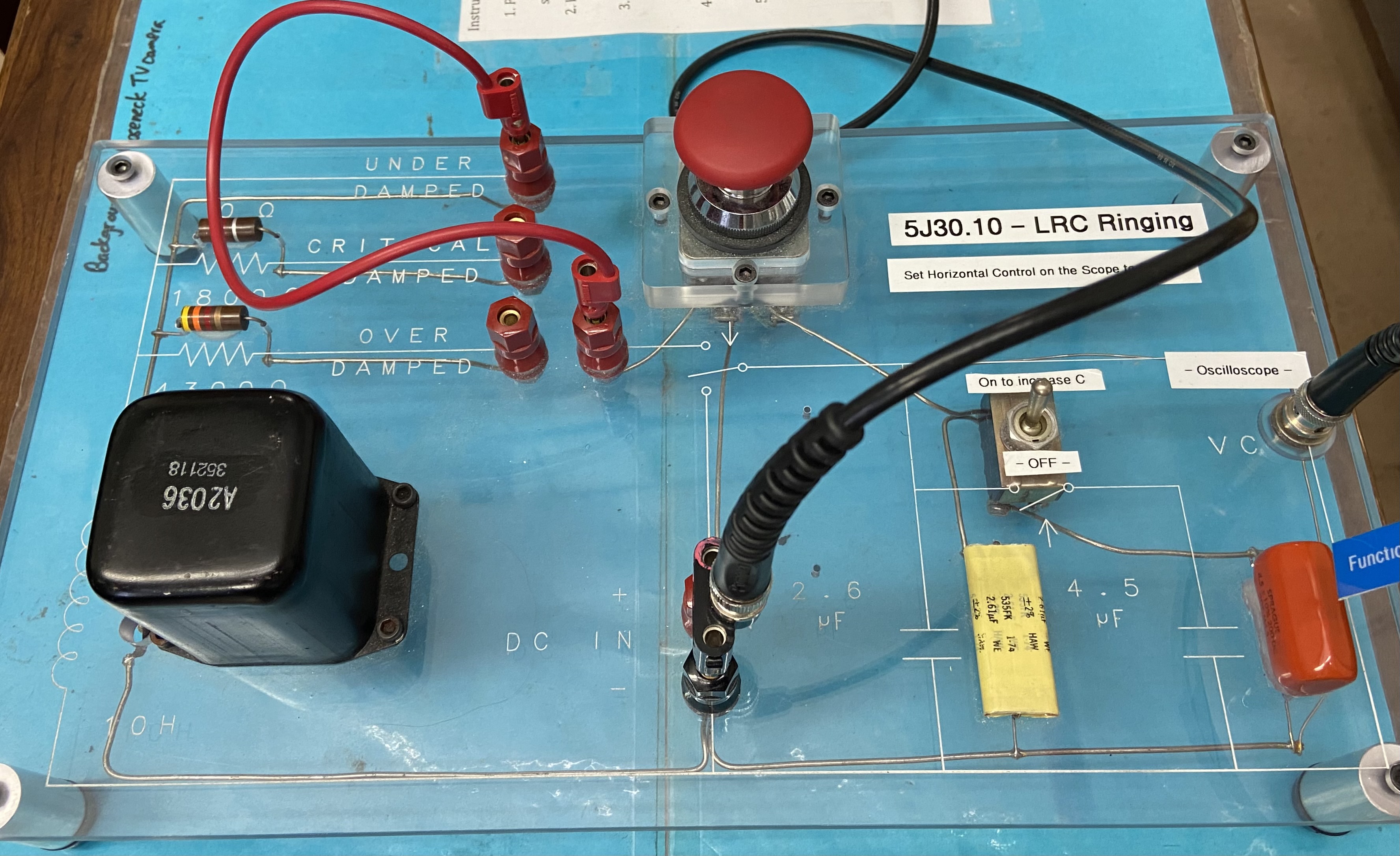
- Adjust circuit board to the desired damped system setting.
- Briefly push down and release the red momentary button on the circuit board.
- To further show the difference between the critically damped system and over damped system, flip the switch on the board to increase the system's capacitance.
Concepts Conveyed:
- Demonstration consists of a digital oscilloscope with a VGA output to the classroom A/V system, 10 Henry inductor, a choice of no resistance, 18000 ohm, and 24000 ohm resistors in the circuit (corresponding to under damped, critically damped, and over damped), a default 2.6 microfarad capacitor, which can be combined with a 4.5 microfarad capacitor.
- The amplitude of oscillation decays more rapidly as damping (resistance) increases, which has an affect on frequency.
Demo Staff Notes:
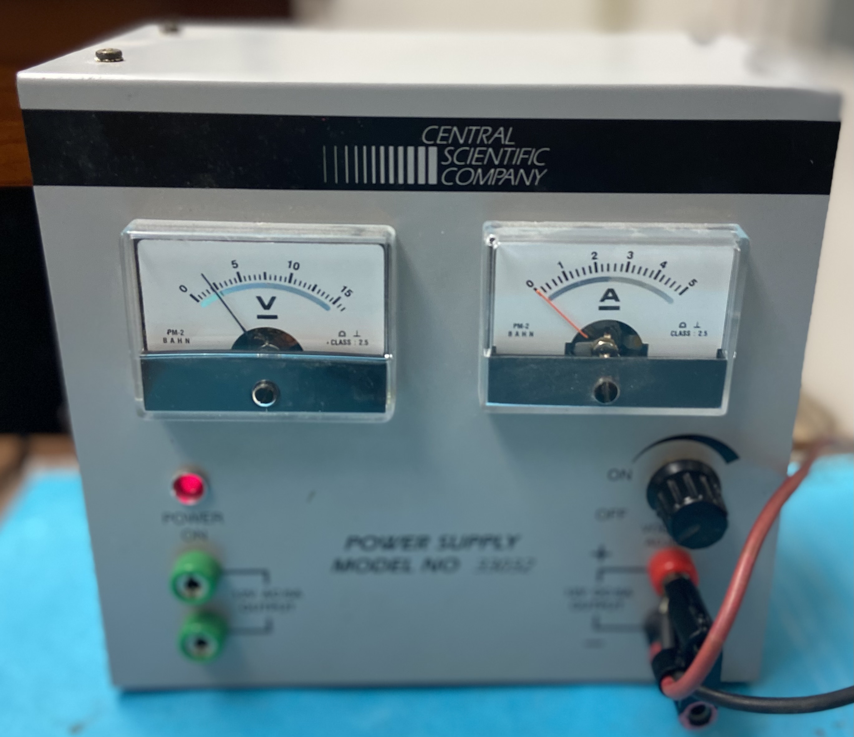
- Ensure all wires are plugged in correctly as shown in the circuit board and power supply photos below.
- After transferring demo to the classroom, turn on the oscilloscope to adjust the settings for faculty.
- Ensure the oscilloscope is set to 500 mV / division for the vertical scale and 200 ms / division for the horizontal scale.
- Set the voltage on the power supply below 2.5 V.
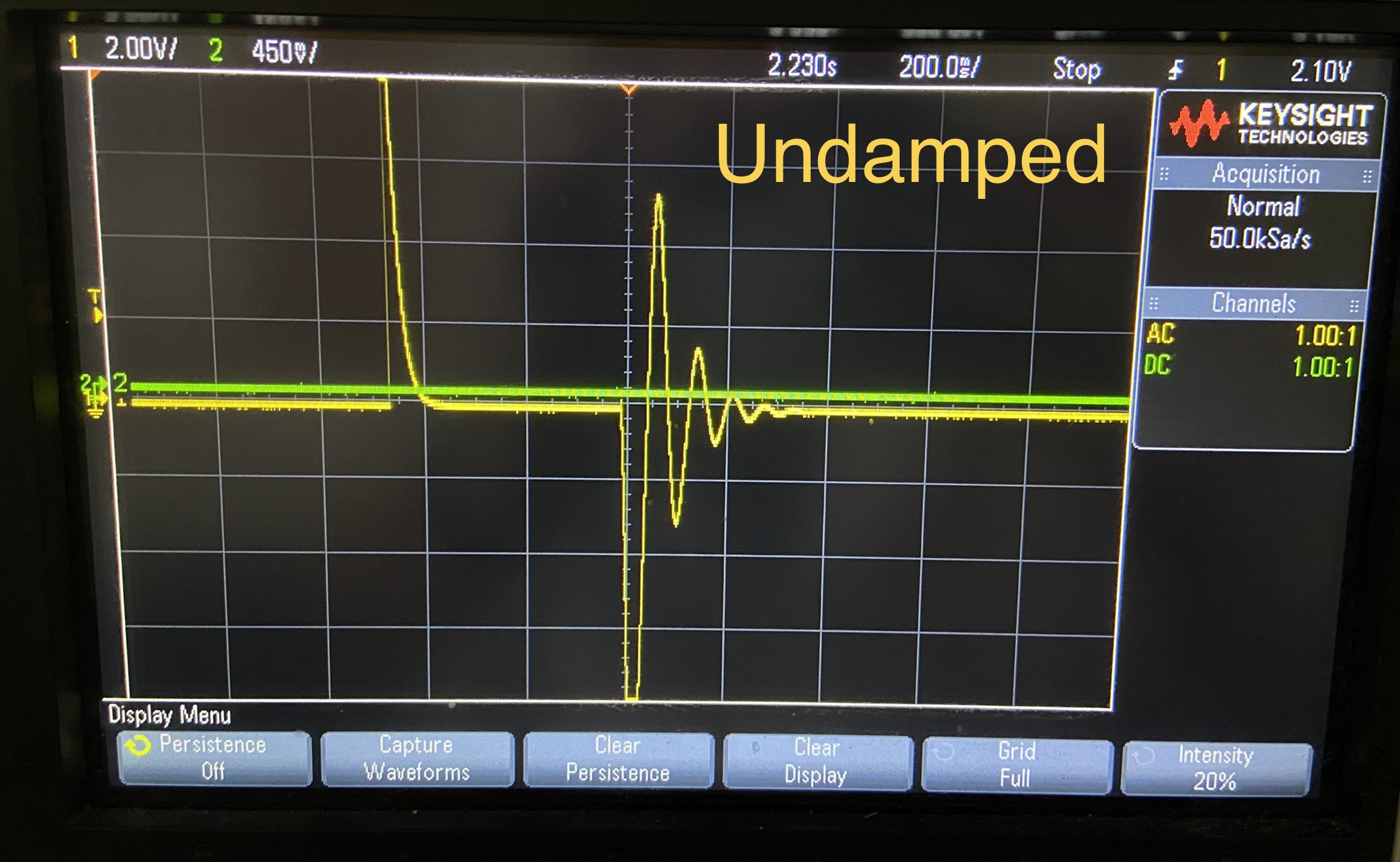
LRC Ring Demo using single capacitor setup.
Last updated on October 12, 2023
